What is VRF, VRF-Lite
Virtual Router Forwarding (“VRF“), It allows router to have many logical routing tables. Services Provider they take this as advantage on it with MPLS, so as to separate the network to Customers.
VLAN = VRF?
Virtual Local Area network & Virtual Router Forwarding, they are both separating the network. BUT
1 is in Layer 2
1 is in Layer 3
VRF-Lite
Running VRF without MPLS & MP-BGP, which is called VRF-lite. So normally it will be used in enterprise or in data center.
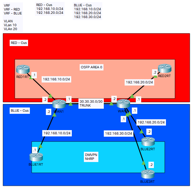
As below Figure 1.1, we will demonstrate VRF-lite
- Separate 2 VRF – RED & BLUE
- RED – we will use OSPF for Daynamic routing
- BLUE – we will use GRE Tunnel & DMVPN
- Local WAN Router – local routing table should have 1 connected link, and no included red & blue.
- RED1RT should be able to see RED2 Route. / Able to Ping
- BLUE1RT should have BLUE2 & BLUE3 DMVPN Peer / Able to Ping
CONFIGURATION
on WAN Router
vrf definition RED
address-family ipv4

vrf definition BLUE
address-family ipv4

in Gi0/0.10
enca dot1q vlan 10
ip address x.x.x.x vrf forwarding RED

in Gi0/1
vrf forwarding RED
in Gi0/2
vrf forwarding BLUE

Router OSPF 1 vrf RED
network x.x.x.x x.x.x.x area 0
on Red side
interface config as general setup

Router OSPF 1
network x.x.x.x x.x.x.x area 0
on BLUE side
interface config as general setup

Create Tunnel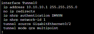
SHOWN
As we are using VRF-Lite, we can use duplication IP address on Interface, GI0/0 , GI0/1 & GI0/2
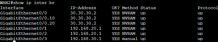
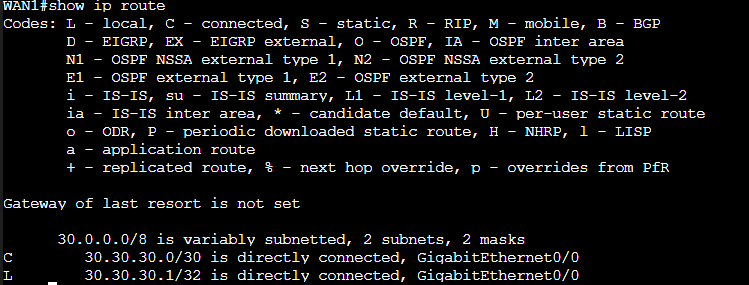
On WAN Router, Local Routing Table, it only has 1 Connection information. But it is not included the VRF.
VRF-lite
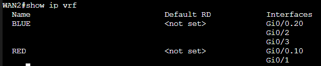
we can see VRF has been assigned to the interface.
On WAN Router, we are using Virtual Router, it separate the routing table at the same router.
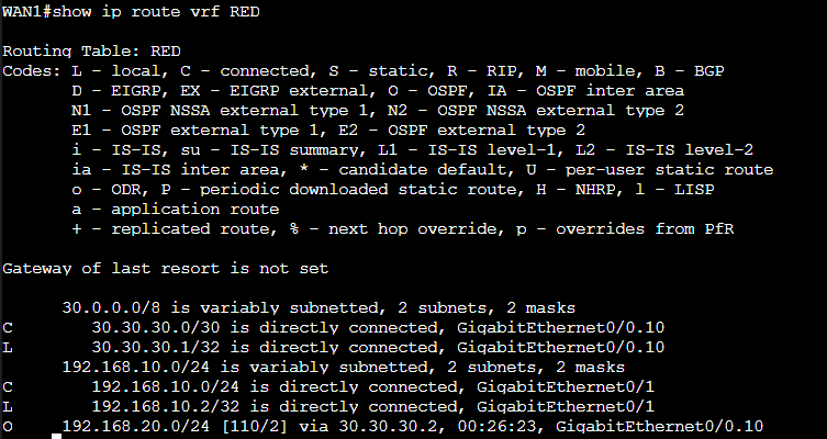
“IP Routing vrf xxx” <- this command which will provide different vrf routing table informaiton.
In RED Routing Tables, It is including OSPF Dynamic Routing Protocol.
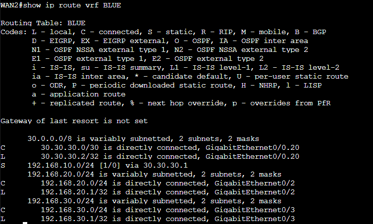
In BLUE Routing Tables, Between WAN Routers, I can’t use Dynamic Routing with some reason. So I have applied static route in between. (“192.168.10.0 via 30.30.30.1”)
DMVPN
BLUE1RT act as HUB
BLUE2RT & BLUE3 RT act ac Spoke
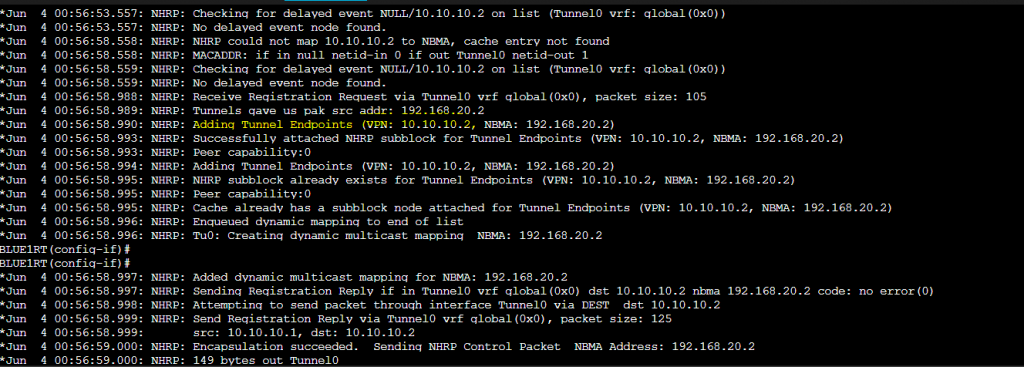
As below, We can see DMVPN has been establish. By using “debug nhrp”. We can see there is a message which is indicated. An Tunel endpoints has been adding.
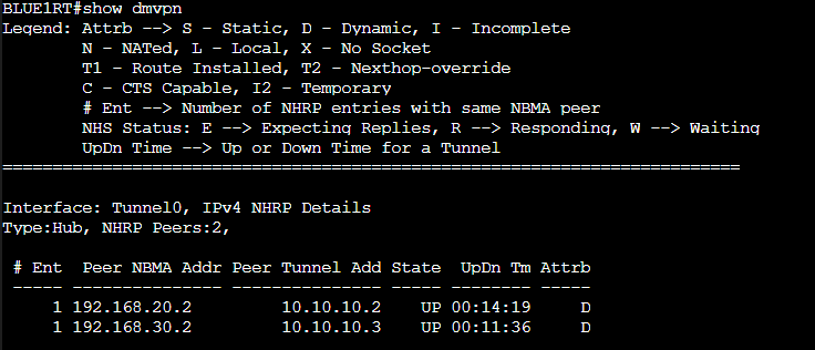
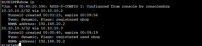
We can see there is 2 peers on the Hub (“BLUE1RT”), including tunnel address and physical interface IP address.
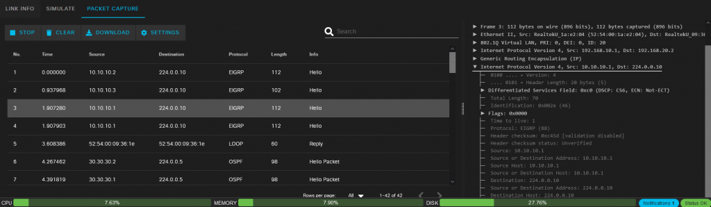
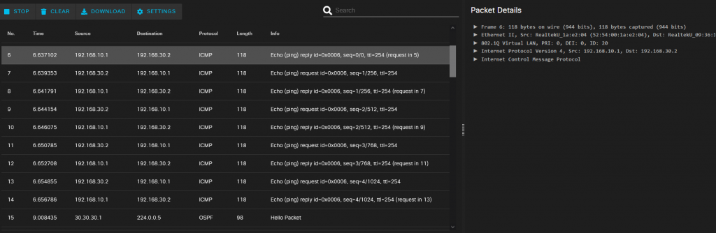
PACKET CAPTURE
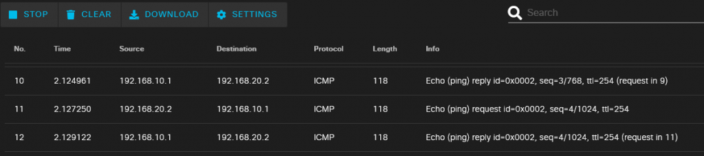
RED -RESULT
From RED1RT (“192.168.10.1”) pinging to RED2RT (“192.168.20.2”) – succ
BLUE -RESULT
Ping from BLUE2RT Tunnel Interface to BLUE1RT loopback interface – Ping succ
In the packet capture, we can see it is a GRE.
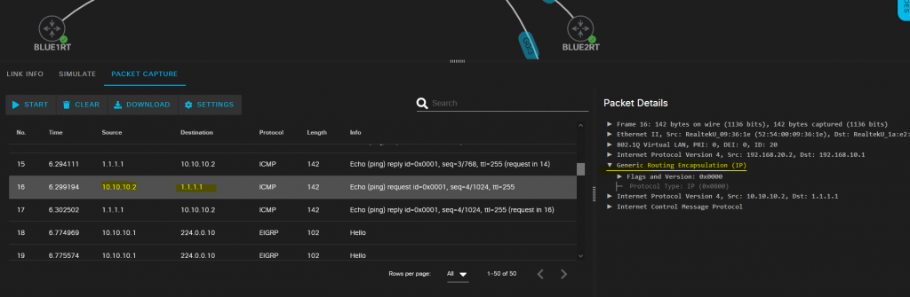
USING EIGRP to learn each BLUE router loop back interface. EIGRP is using Multicast to sending hello packet. As it is through GRE Tunnel, so it is has been encapsulated.