What does MPLS Do for us ? Part 1
Multiprotocol Label Switching (“MPLS”). This is protocol between Layer 2 and Layer 3. Let’s say it is 2.5 Layer.
Why we need MPLS?
How does MPLS work?
What can MPLS help us?
In this lab, we will go through setting up MPLS and to find out more about MPLS.
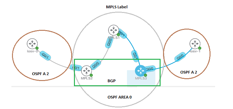
- Setup OSPF between Routers, MPLS1, 2 & 3
- Enable MPLS LDP on those Routers MPLS1, 2 & 3.
- establish BGP relations between MPLS 2 & 3 only
- OSPF Area 2 between MPLS2 + iosv-0 & MPLS3 + iosv-1
- Redistribute Routing OSPF area 2 and BGP
OSPF + MPLS
Between MPLS1-3 Routers, We will created loop back and interface
MPLS1 – LoopBack 0 – 1.1.1.1
172.16.0.0/30
172.16.0.4/30
MPLS2 – LoopBack 0 – 1.1.1.2
172.16.0.0/30
MPLS3 – LoopBack 0 – 1.1.1.3
172.16.0.4/30
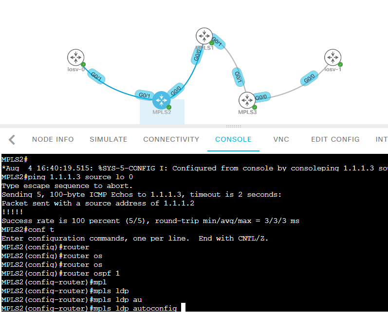
Also on those Routers, Enable MPLS LDP ( Label Distribution Protocol). As this is a small network, We use “AutoConfig”.
MPLS in OSPF Area 0.
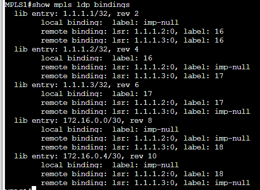
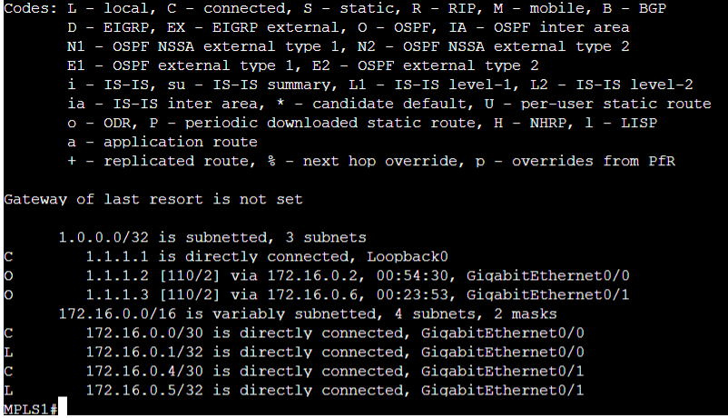
Once it is done. You should see the routing table, each routers can see loopback via OSPF.
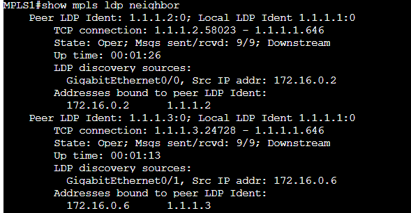
Also you can see LDP Neighbor by typing “Show mpls ldp neighbor”
BGP + VRF + OSPF Area 2
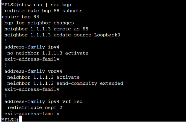
Now we will created a BGP session between MPLS2 & MPLS3 – Neighbor each other Loopback interface.
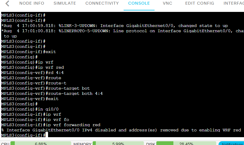
- create VRF , We call “red” here
- enable VRF on the interface toward the routers “edge1” & “edge2”
- On those interface also need enable OSPF on both Routers but Area 2.
- On BGP – enable vrf on BGP also redistribute OSPF 2
- On OSPF redistribute BGP
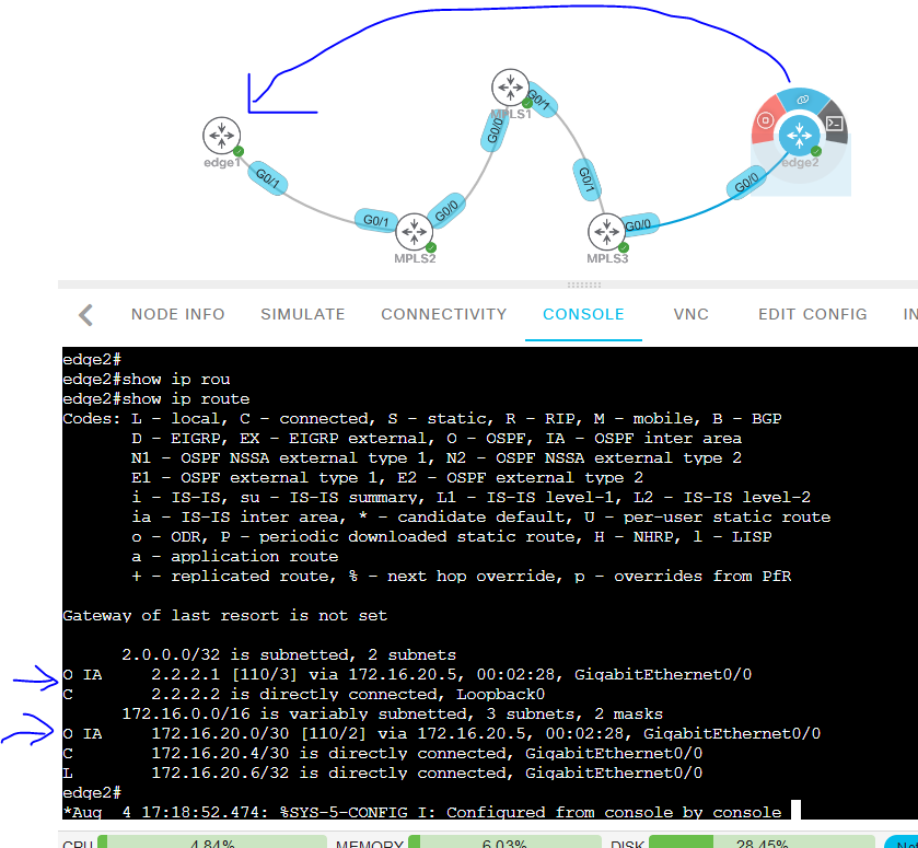
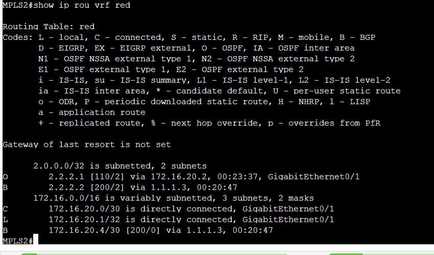
When it is successful.
Edge 1 routing table should able to see the Routing to “Edge 2” via OSPF IA
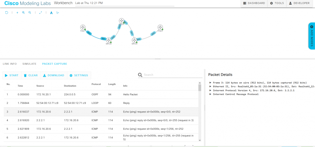
Traffic through MPLS
Now we will ping
From Edge2 to Edge1
From Edge2 GI0/0 to Edge1 Gi0/1 172.16.20.1
From Edge2 GI0/0 to Edge1 Loopback 2.2.2.1
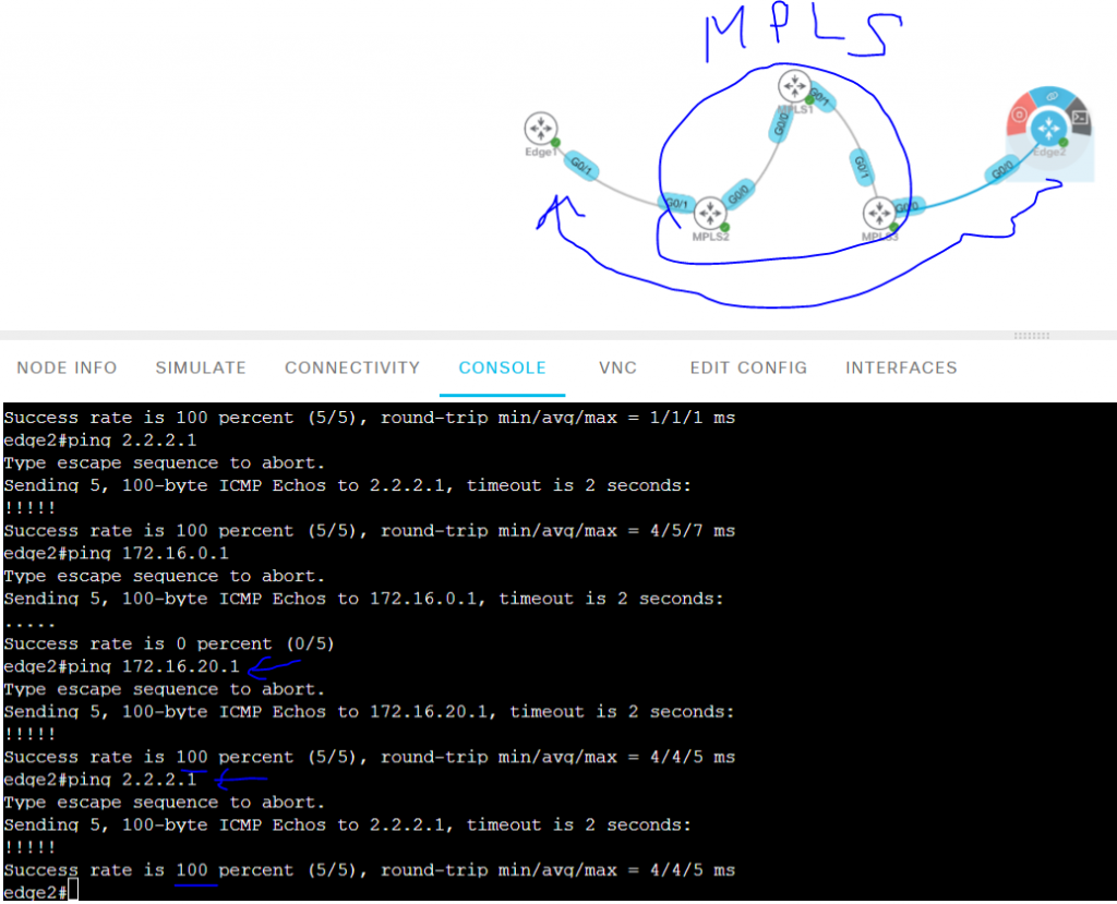
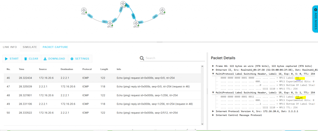
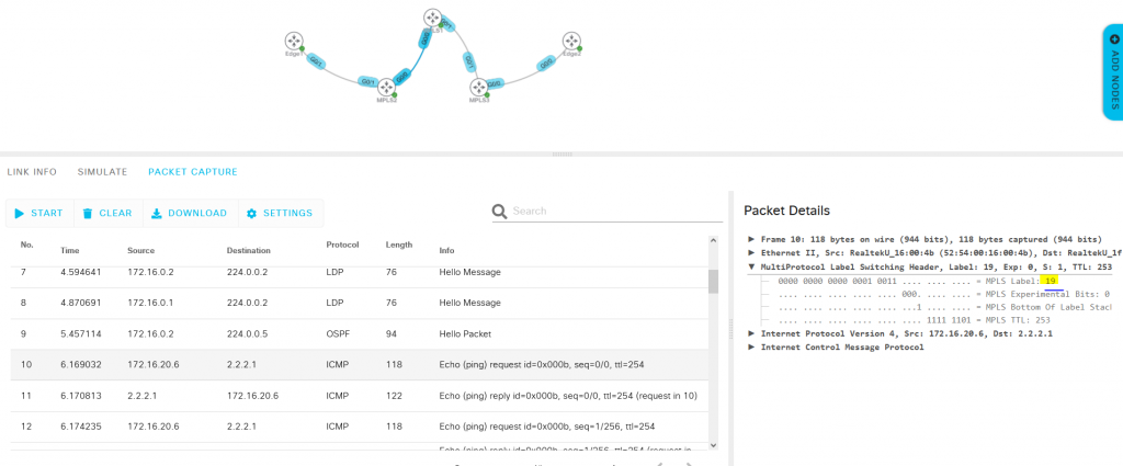
Image below packet capture, we can see packet labeling.
When the packet sending to MPLS1 , We see 2 label in the packet. Label 16 & 19.
When MPLS1 received it, and send to MPLS2. It will removed Label 16, Keep Label 19 and forward to the next target switch.
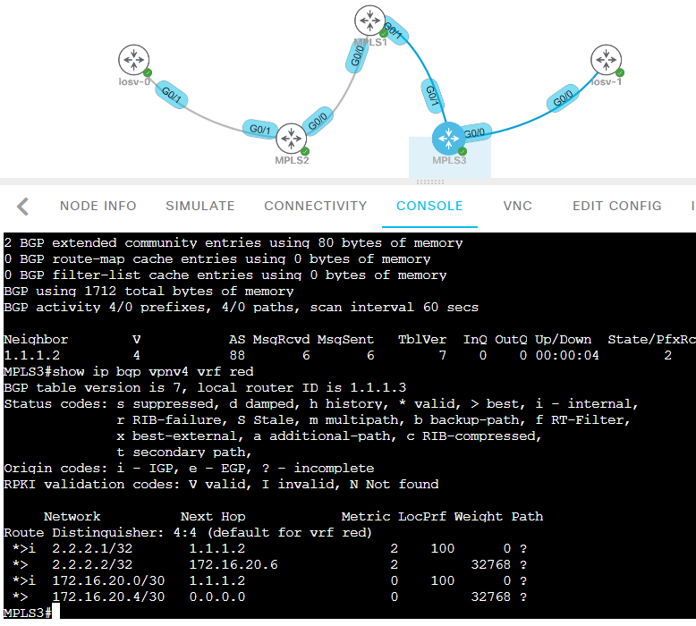
MP BGP
This in lab, we are using MP BGP VPN.
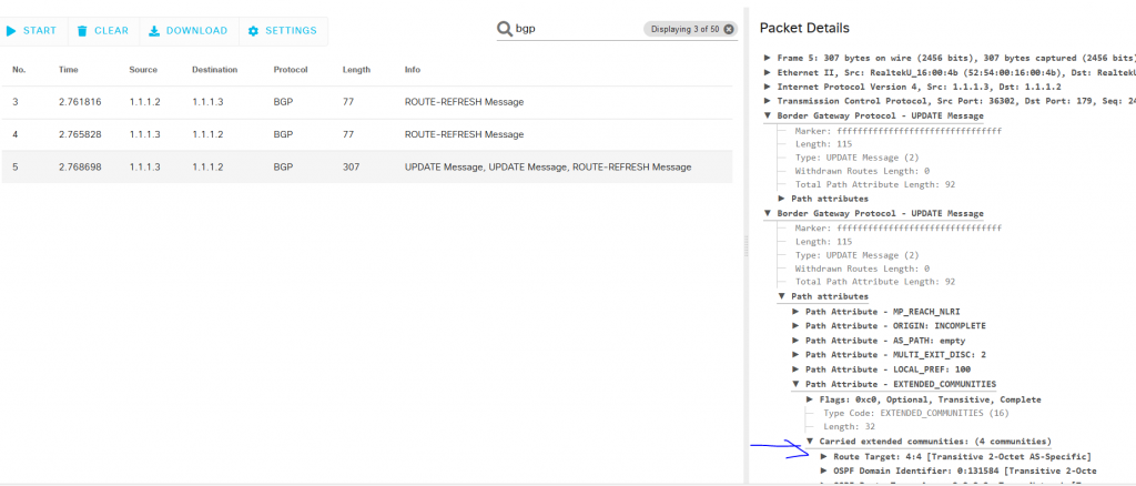
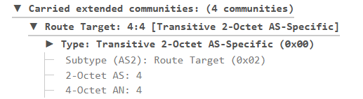
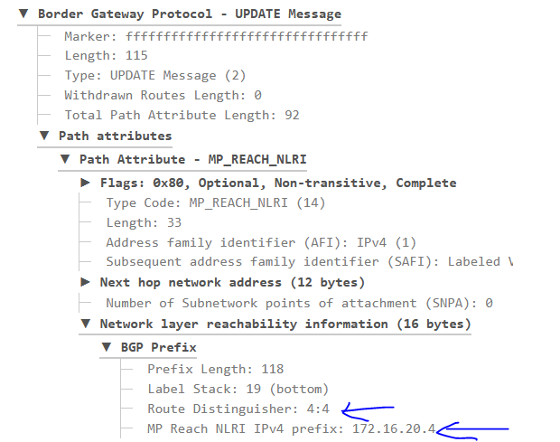
RD VRF has been applied, RD 4:4 & Router-targe both 4:4
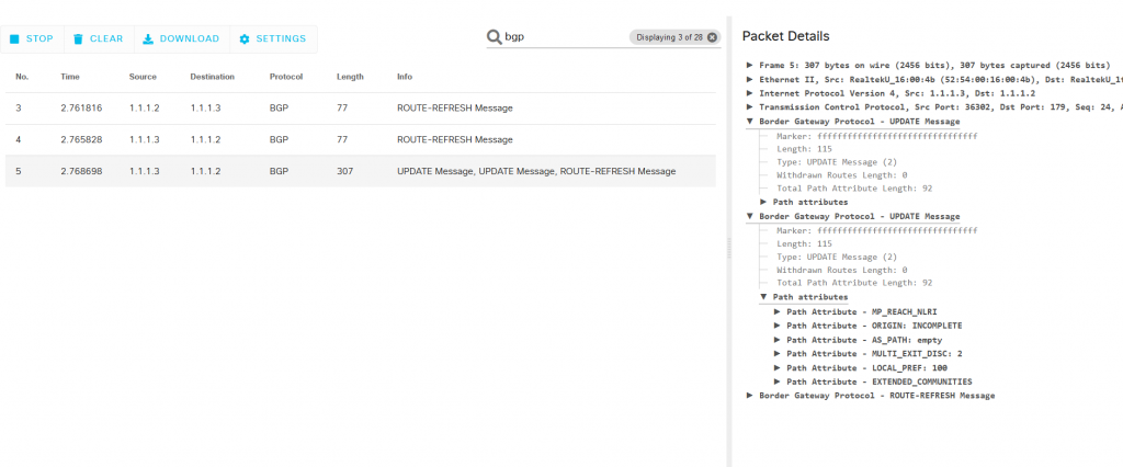
When we use packet capture, we can see the RD information. When MPLS3 sending BGP updates message to MPLS2.